1 - Eucalyptus Architecture Overview
This topics describes the relationship of the components in a Eucalyptus installation.
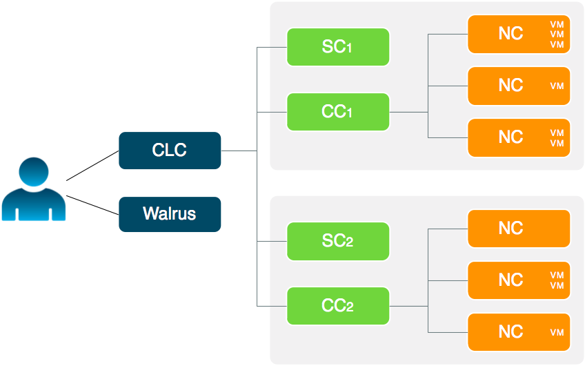
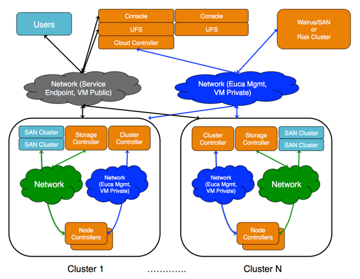 The cloud components: Cloud Controller (CLC) and Walrus, as well as user components: User-Facing Services (UFS) and the Management Console, communicate with cluster components: the Cluster Controllers (CCs) and Storage Controllers (SCs). The CCs and SCs, in turn, communicate with the Node Controllers (NCs). The networks between machines hosting these components must be able to allow TCP connections between them.
Ceph provides an alternative to Walrus as an object storage provider, and can also be used as a block storage provider (EBS).
2 - Plan Your Hardware
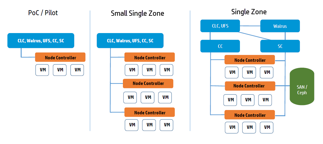
This topic describes ways you can install Eucalyptus services on your physical servers.You can run Eucalyptus services in any combination on the various physical servers in a data center. For example, you can install the Cloud Controller (CLC), Walrus, CC, and SC on one host machine, and NCs on one or more host machines. Or you can install each service on an independent physical server. This gives each service its own local resources to work with.
Often in installation decisions, you must trade deployment simplicity for performance. For example, if you place all cloud (CLC) and zone (CC) services on a single machine, it makes for simple administration. This is because there is only one machine to monitor and control for the Eucalyptus control services. But, each service acts as an independent web service; so if they share a single machine, the reduced physical resources available to each service might become a performance bottleneck.
3 - Plan Services Placement
Cloud Services
The main decision for cloud services is whether to install the Cloud Controller (CLC) and Walrus on the same server. If they are on the same server, they operate as separate web services within a single Java environment, and they use a fast path for inter-service communication. If they are not on the same server, they use SOAP and REST to work together.
Sometimes the key factor for cloud services is not performance, but server cost and data center configuration. If you only have one server available for the cloud, then you have to install the services on the same server.
All services should be in the same data center. They use aggressive time-outs to maintain system responsiveness so separating them over a long-latency, lossy network link will not work.
User Services
The User Facing Services (UFS) handle all of the AWS APIs and provide an entry point for clients and users interacting with the Eucalyptus cloud. The UFS and the Management Console are often hosted on the same machine since both must be accessible from the public, client-facing network.
You may optionally choose to have redundant UFS and Management Console host machines behind a load balancer.
Zone Services
The Eucalyptus services deployed in the zone level of a Eucalyptus deployment are the Cluster Controller (CC) and Storage Controller (SC).
You can install all zone services on a single server, or you can distribute them on different servers. The choice of one or multiple servers is dictated by the demands of user workload in terms of number of instances (CC) and EBS volume access (SC).
Things to consider for CC placement:
Place the CC on a server that has TCP/IP connectivity to the front-end servers and the NC servers in its zone.
Each CC can manage a maximum of 4000 instances.
Things to consider for SC placement:
The SC host machine must always have TCP/IP connectivity to the CLC and be able use multicast to the CLC.
The SC must have TCP/IP connectivity to the UFS/OSG hosts for uploading snapshots into the object store. (The SC does not require connectivity directly to users, it is an internal component and does not serve user EBS API requests; that job is done by the UFS.)
The SC must be reachable via TCP/IP from all NCs in the zone within which the SC is registered. The SC and NC exchange tokens to authorize volume attachment, so they must be able to directly communicate. The SC provides the NCs with network access to the dynamic block volumes on the SC’s storage (if the SC is configured for overlay local filesystem or DAS-JBOD).
IF using Ceph the SC must also have TCP/IP connectivity to the Ceph cluster.
If you are going to use overlay local filesystem or DAS-JBOD configurations to export local SC storage for EBS, then SC storage should consist of a fast, reliable disk pool (either local file-system or block-attached storage) so that the SC can create and maintain volumes for the NCs. The capacity of the disk pool should be sufficient to provide the NCs with enough space to accommodate all dynamic block volumes requests from end users.
Node Services
The Node Controllers are the services that comprise the Eucalyptus backend. All NCs must have network connectivity to whatever machine(s) host their EBS volumes. Hosts are either a Ceph deployment or the SC.
4 - Plan Disk Space
We recommend that you choose a disk for the Walrus that is large enough to hold all objects and buckets you ever expect to have, including all images that will ever be registered to your system, plus any Amazon S3 application data. For heavy S3 usage, Riak CS is a better choice for object storage.
Note
We recommend that you use LVM (Logical Volume Manager). If you run out of disk space, LVM allows you to add disks and migrate the data.| Service | Directory | Minimum Size |
|---|
| Cloud Controller (CLC)CLC logging | /var/lib/eucalyptus/db/var/log/eucalyptus | 20GB2GB |
| WalrusWalrus logging | /var/lib/eucalyptus/bukkits/var/log/eucalyptus | 250GB2GB |
| Storage Controller (SC) (EBS storage) This disk space on the SC is only required if you are not using Ceph. For DAS the space must not be used by an existing filesystem. | /var/lib/eucalyptus/volumes/var/log/eucalyptus | 250GB |
| User-Facing Services (UFS)UFS logging | /var/lib/eucalyptus/var/log/eucalyptus | 5GB 2GB |
| Management ConsoleConsole logging | /var/log/eucalyptus-console | 5GB 2GB |
| Cluster Controller (CC)CC logging | /var/lib/eucalyptus/CC/var/log/eucalyptus | 5GB2GB |
| Node Controller (NC)NC logging | /var/lib/eucalyptus/instances/var/log/eucalyptus | 250GB2GB |
If necessary, create symbolic links or mount points to larger filesystems from the above locations. Make sure that the ’eucalyptus’ user owns the directories.
6 - Plan Networking Modes
Plan Networking Modes
These networking modes are designed to allow you to choose an appropriate level of security and flexibility for your cloud. The purpose is to direct Eucalyptus to use different network features to manage the virtual networks that connect VMs to each other and to clients external to Eucalyptus .
Eucalyptus networking modes are generally modeled after AWS networking capabilities. In legacy AWS accounts, you have the ability to choose EC2 Classic network mode or VPC network mode. New AWS accounts do not have this flexibility and are forced into using VPC. Eucalyptus VPCMIDO mode is similar to AWS VPC in that it allows users to fully manage their cloud network, including the definition of a Classless Inter-Domain Routing (CIDR) block, subnets, and security groups with rules for additional protocols beyond the default three (UDP, TCP, and ICMP) available in EC2 Classic networking.
Your choice of networking mode depends on the following considerations:
- Does your cloud need to mimic behavior in your AWS account? If you need EC2-Classic behavior, select EDGE mode. If you need EC2-VPC behavior, select VPCMIDO mode.
- Do you need to create security group rules with additional protocols (e.g., all protocols, RDP, XTP, etc.)? If so, choose VPCMIDO mode.
- If there is no specific requirement for either mode, then VPCMIDO mode is recommended given its flexibility and networking features.
Each networking mode is described in the following sections.
6.1 - About Eucanetd
The eucanetd service implements artifacts to manage and define Eucalyptus cloud networking. Eucanetd runs alongside the CLC or NC services, depending on the configured networking mode. Eucanetd manages network functionality. For example:
- Installs network artifacts (iptables, ipsets, ebtables, dhcpd)
- Performs state management for the installed network artifacts
- Updates network artifact configuration as needed
- In VPCMIDO mode:
- Interacts with MidoNet via the MidoNet API
- Defines network artifacts in MidoNet
Where to deploy eucanetd
Deploy eucanetd depending on the selected network mode:
| Host Machine | EDGE mode | VPCMIDO mode |
|---|
| CLC | No | Yes |
| NC | Yes | No |
When required for a mode eucanetd should be deployed on all hosts for that service.
6.2 - Understanding Eucalyptus EDGE Mode
In EDGE networking mode, the components responsible for implementing Eucalyptus VM networking artifacts are running at the edge of a Eucalyptus deployment: the Linux host machines acting as Node Controllers (NCs). On each NC host machine, a Eucalyptus stand-alone service, eucanetd, runs side-by-side with the NC service. The eucanetd service receives dynamically changing Eucalyptus networking views and is responsible for configuring the Linux networking subsystem to reflect the latest view.
EDGE networking mode integrates with your existing network infrastructure, allowing you to inform Eucalyptus , through configuration parameters for EDGE mode, about the existing network, which Eucalyptus then will consume when implementing the networking view.
EDGE networking mode integrates with two basic types of pre-existing network setups:
- One flat IP network used to service component systems, VM public IPs (elastic IPs), and VM private IPs.
- Two networks, one for components and VM public IPs, and the other for VM private IPs.
Note
EDGE networking mode integrates with networks that already exist. If the network, netmask, and router don’t already exist, you must create them outside before configuring EDGE mode.EDGE Mode Requirements
- Each NC host machine must have an interface configured with an IP on a VM public and a VM private network (which can be the same network).
- There must be IP connectivity from each NC host machine (where eucanetd runs) and the CLC host machine, so that network path from instances to the metadata server (running on the CLC host machine) can be established.
- There must be a functioning router in place for the private network. This router will be the default gateway for VM instances.
- The private and public networks can be the same network, but they can also be separate networks.
- The NC host machines need a bridge configured on the private network, with the bridge interface itself having been assigned an IP from the network.
- If you’re using a public network, the NC host machines need an interface on the public network as well (if the public and private networks are the same network, then the bridge needs an IP assigned on the network).
- If you run multiple zones, each zone can use the same network as its private network, or they can use separate networks as private networks. If you use separate networks, you need to have a router in place that is configured to route traffic between the networks.
- If you use private addressing only, the CLC host machine must have a route back to the VM private network.
EDGE Mode Limitations
- Global network updates (such as security group rule updates, security group VM membership updates, and elastic IP updates) are applied through an “eventually consistent” mechanism, as opposed to an “atomic” mechanism. That is, there may be a brief period of time where one NC has the new state implemented but another NC has the previous state implemented.
- Mappings between VM MAC addresses and private IPs are strictly enforced. This means that instances cannot communicate using addresses the cloud has not assigned to them.
6.3 - Understanding VPCMIDO and MidoNet
This topic describes MidoNet components and their Eucalyptus deployment options, which provide support for VPC on Eucalyptus. Eucalyptus VPCMIDO mode resembles the Amazon Virtual Private Cloud (VPC) product wherein the network is fully configurable by users. In Eucalyptus, it is implemented with a Software-Defined Networking (SDN) technology called MidoNet. MidoNet is a network virtualization platform for Infrastructure-as-a-Service (IaaS) clouds that implements and exposes virtual network components as software abstractions, enabling programmatic provisioning of virtual networks.
This network mode requires configuration of MidoNet in order to make cloud networking functional. It offers the most advanced networking capabilities and therefore it is recommended to be used on all new Eucalyptus installations.
MidoNet Components
A MidoNet deployment consists of four types of nodes (according to their logical functions or services offered), connected via four IP networks as depicted in Figure 1. MidoNet does not require any specific hardware, and can be deployed in commodity x86_64 servers. Interactions with MidoNet are accomplished through Application Programming Interface (API) calls, which are translated into (virtual) network topology changes. Network state information is stored in a logically centralized data store, called the Network State Database (NSDB), which is implemented on top of two open-source distributed coordination and data store technologies: ZooKeeper and Cassandra. Implementation of (virtual) network topology is realized via cooperation and coordination among MidoNet agents, which are deployed in nodes that participate in MidoNet.
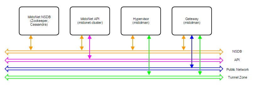 Figure 1: Logical view of a MidoNet deployment. Four components are connected via four networks.
Node types:
- MidoNet Network State Database (NSDB): consists of a cluster of ZooKeeper and Cassandra. All MidoNet nodes must have IP connectivity with NSDB.
- MidoNet API: consists of MidoNet web app. Exposes MidoNet REST APIs.
- Hypervisor: MidoNet agent (Midolman) are required in all Hypervisors to enable VMs to be connected via MidoNet overlay networks/SDN.
- Gateway: Gateway nodes are connected to the public network, and enable the network flow from MidoNet overlays to the public network.
Physical Networks:
- NSDB: IP network that connects all nodes that participate in MidoNet. While NSDB and Tunnel Zone networks can be the same, it is recommended to have an isolated (physical or VLAN) segment.
- API: in deployments only eucanetd/CLC needs access to the API network. Only “special hosts/processes” should have access to this network. The use of “localhost” network on the node running CLC/eucanetd is sufficient and recommended in deployments.
- Tunnel Zone: IP network that transports the MidoNet overlay traffic ( VM traffic), which is not “visible” on the physical network.
- Public network: network with access to the Internet (or corporate/enterprise) network.
MidoNet Deployment Scale
Three reference architectures are presented in this document, ordered by complexity and size:
- Proof-of-Concept (PoC)
- Production: Small
- Production: Large
Production: Large reference architecture represents the most complete and recommended deployment model of MidoNet for Eucalyptus. Whenever possible (such as when resources are available), deployments should closely match with the Production: Large reference architecture (even on small scale clouds).
All MidoNet components are designed and implemented to horizontally scale. Therefore, it is possible to start small and add resources as they become available.
Eucalyptus with MidoNet
A Eucalyptus with MidoNet deployment consists of the following components:
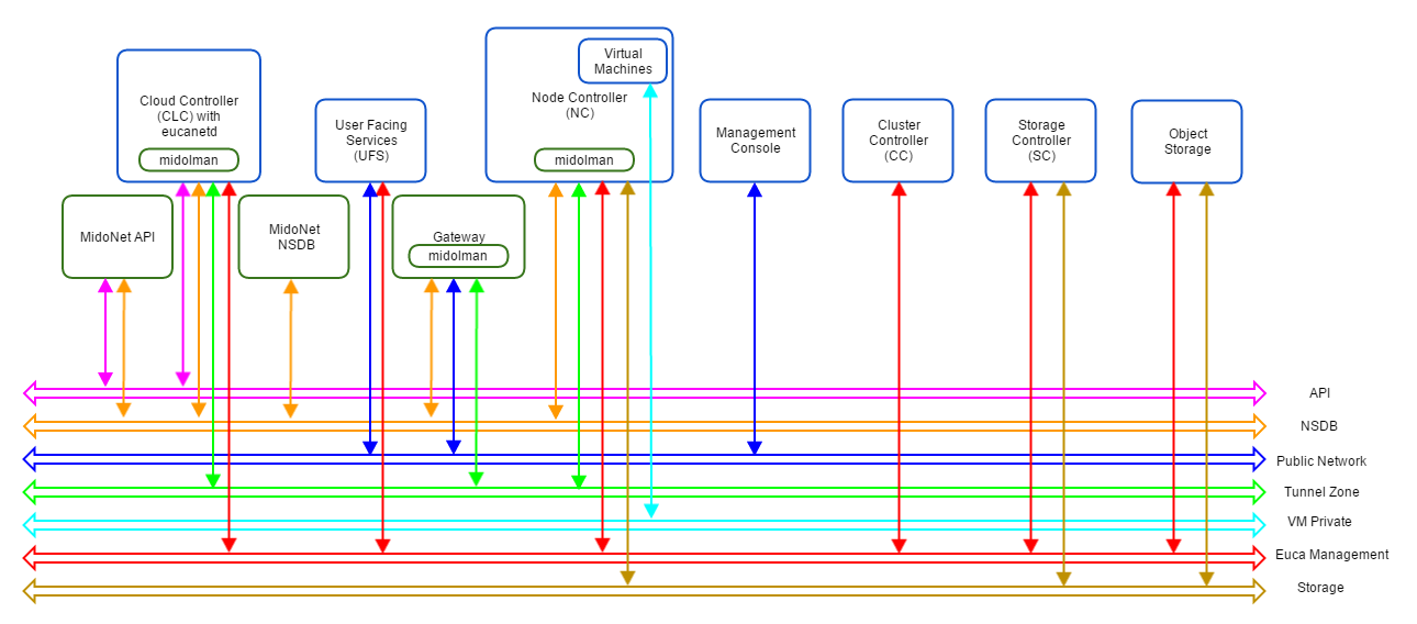 Figure 2: Logical view of a Eucalyptus with MidoNet deployment. VM private network is created/virtualized by MidoNet, and ‘software-defined’ by eucanetd. Ideally, each component and network should have its own set of independent resources. In practice, components are grouped and consolidated into a set of servers, as detailed in different reference architectures.
MidoNet components, Eucalyptus components, and three extra networks are present.
Proof of Concept (PoC)
The PoC reference architecture is designed for very small and transient workloads, typical in development and testing environments. Quick deployment with minimal external network requirements are the key points of PoC reference architecture.
Requirements
Servers:
- Four (4) or more modern Intel cores or AMD modules - exclude logical cores that share CPU resources from the count (Hyperthreads and AMD cores within a module)
- 2GB of RAM reserved for MidoNet Agent (when applicable)
- 4GB of RAM reserved for MidoNet NSDB (when applicable)
- 4GB of RAM reserved for MidoNet API (when applicable)
- 30GB of free disk space for NSDB (when applicable)
Physical Network:
- One (1) 1Gbps IP Network
- A range or list of public IP addresses (Euca_public_IPs)
- Internet Gateway
Limits:
- Ten (10) MidoNet agents (i.e., 1 Gateway node, 1 CLC, and 8 NCs)
- One (1) MidoNet Gateway
- No fail over, fault tolerance, and/or network load balancing/sharing
Deployment Topology
- Single server with all MidoNet components (NSDB, API, and Midolman), and with CLC/eucanetd
- A server acting as MidoNet Gateway - when BGP terminated links are used, this node must not be co-located with CLC/eucanetd (in a proxy_arp setup described below, it is possible to consolidate CLC/eucanetd with MidoNet Gateway). This is due to incompatibilities in CentOS/RHEL7 netns (used by eucanetd), and bgpd (started by Midolman when BGP links are configured).
- Hypervisors with Midolman
- One IP network handling NSDB, Tunnel Zone, and Public Network traffic
- API communication via loopback/localhost network
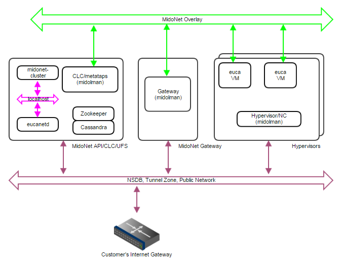 Figure 3: PoC deployment topology. A single IP network carries NSDB, Tunnel Zone, and Public Network traffic. A single server handles MidoNet NSDB, API (and possibly Gateway) functionality.
MidoNet Gateway Bindings
Three ways to realize MidoNet Gateway bindings are discussed below, starting with the most recommended setup.
Public CIDR block(s) allocated for Eucalyptus (Euca_Public_IPs) needs to be routed to MidoNet Gateway by the customer network - this is an environment requirement, outside of control of both MidoNet and Eucalyptus systems. One way to accomplish this is to have a BGP terminated link available. MidoNet Gateway will establish a BGP session with the customer router to: (1) advertise Euca_Public_IPs to the customer router; and (2) get the default route from the customer router.
If a BGP terminated link is not available, but the routing of Euca_Public_IPs is delegated to MidoNet Gateway (configuration of customer routing infrastructure), similar setup can be used. In such scenario, static routes are configured on the customer router (to route Euca_Public_IPs to MidoNet Gateway), and on MidoNet (to use the customer router as the default route).
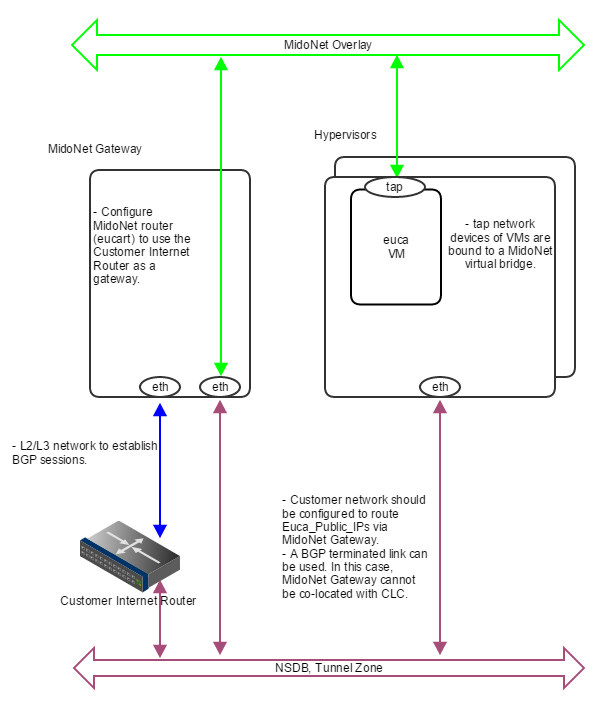 Figure 4: How servers are bound to MidoNet in a PoC deployment with BGP. A BGP terminated link is required: the gateway node eth device is bound to MidoNet virtual router (when BGP is involved, the MidoNet Gateway and Eucalyptus CLC cannot be co-located). Virtual machine tap devices are bound to MidoNet virtual bridges.
If routed Euca_Public_IPs are not available, static routes on all involved nodes (L2 connectivity is required among nodes) can be used as illustrated below.
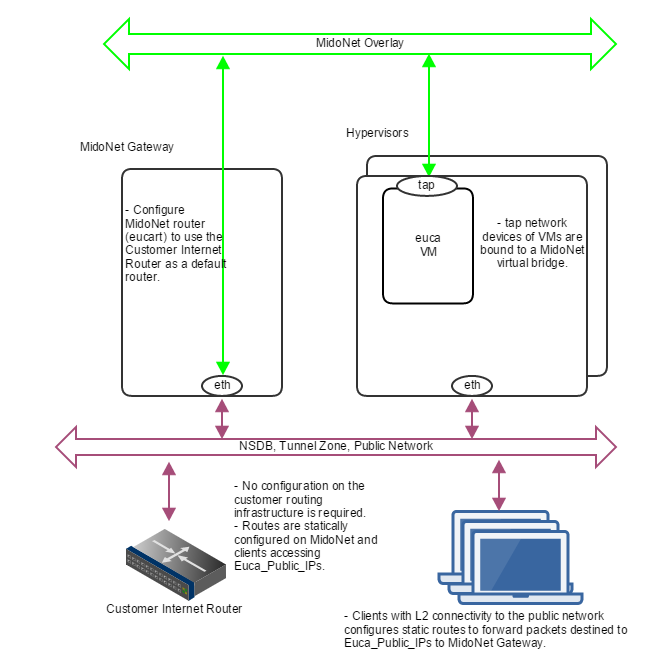 Figure 5: How servers are bound to MidoNet in a PoC deployment without routed Euca_Public_IPs. Clients that need communication with Euca_Public_IPs configure static routes using MidoNet Gateway as the router. MidoNet Gateway configures a static default route to customer router.
In the case nodes outside the public network broadcast domain (L2) needs to access Euca_Public_IPs, a setup using proxy_arp, as illustrated below, can be used.
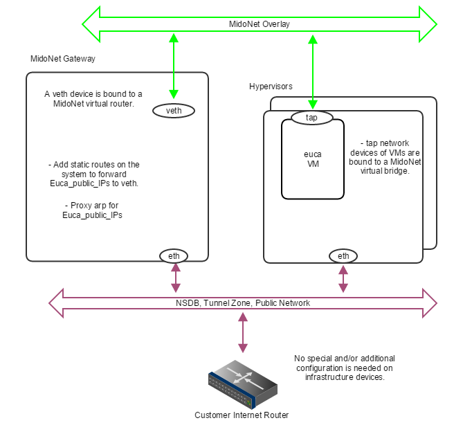 Figure 6: How servers are bound to MidoNet in a PoC deployment with proxy_arp. When routed Euca_Public_IPs are not available, the gateway node should proxy arp for public IP addresses allocated for Eucalyptus , and forward to a veth device that is bound to a MidoNet virtual router. Virtual machine tap devices are bound to MidoNet virtual bridges.
Production: Small
The Production: Small reference architecture is designed for small scale production quality deployments. It supports MidoNet NSDB fault tolerance (partial failures), and limited MidoNet Gateway failover and load balancing/sharing.
Border Gateway Protocol (BGP) terminated uplinks are recommended for production quality deployments.
Requirements
Servers:
- Four (4) or more modern Intel cores or AMD modules - exclude logical cores that share CPU resources from the count (Hyperthreads and AMD cores within a module) - for gateway nodes, 4 or more cores should be dedicated to MidoNet agent (Midolman)
- 4GB of RAM reserved for MidoNet Agent (when applicable), 8GB for Gateway nodes
- 4GB of free RAM reserved for MidoNet NSDB (when applicable)
- 4GB of free RAM reserved for MidoNet API (when applicable)
- 30GB of free disk space for NSDB (when applicable)
- Two (2) 10Gbps NICs per server
- Three (3) servers dedicated to MidoNet NSDB
- Two (2) servers as MidoNet Gateways
Physical Network:
- One (1) 10Gbps IP Network for public network (if upstream links are 1Gbps, this could be 1Gbps)
- One (1) 10Gbps IP Network for Tunnel Zone and NSDB
- Public Classless Inter-Domain Routing (CIDR) block (Euca_public_IPs)
- Two (2) BGP terminated uplinks
Limits:
- Thirty two (32) MidoNet agents (i.e., 2 Gateway nodes and 30 Hypervisors)
- Two (2) MidoNet Gateways
- Tolerate 1 NSDB server failure
- Tolerate 1 MidoNet Gateway/uplink failure
- Limited uplinks load sharing/balancing
Deployment Topology
- A 3-node cluster for NSDB (co-located ZooKeeper and Cassandra)
- eucanetd co-located with MidoNet API Server
- Two (2) MidoNet Gateway Nodes
- Hypervisors with Midolman
- One 10Gbps IP network handling NSDB and Tunnel Zone traffic
- One 10Gbps IP Network handling Public Network traffic
- API communication via loopback/localhost network
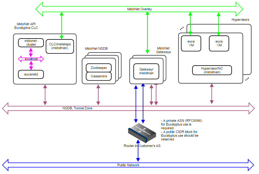 Figure 7: Production:Small deployment topology. A 10Gbps IP network carries NSDB and Tunnel Zone traffic. Another 10Gbps IP network carries Public Network traffic. A 3-node cluster for NSDB tolerates 1 server failure, and 2 gateways enable network failover and limited load balancing/sharing.
 Figure 8: How servers are bound to MidoNet in a Production:Small deployment. Gateway Nodes have physical devices bound to a MidoNet virtual router. These devices should have L2 and L3 connectivity to the Customer’s Router, and with BGP terminated links. Virtual machine tap devices are bound to MidoNet virtual bridges.
NSDB Data Replication
- NSDB is deployed in a cluster of 3 nodes
- ZooKeeper and Cassandra both have built-in data replication
- One server failure is tolerated
MidoNet Gateway Failover
- Two paths are available to and from MidoNet, and failover is handled by BGP
MidoNet Gateway Load Balancing and Sharing
- Load Balancing from MidoNet is implemented by MidoNet agents (Midolman): ports in a stateful port group with default routes out are used in a round-robin fashion.
- Partial load sharing from the Customer’s router to MidoNet can be accomplished by:
Production: Large
The Production:Large reference architecture is designed for large scale (500 to 600 MidoNet agents) production quality deployments. It supports MidoNet NSDB fault tolerance (partial failures), and MidoNet Gateway failover and load balancing/sharing.
Border Gateway Protocol (BGP) terminated uplinks are required. Each uplink should come from an independent router.
Requirements:
- Eight (8) or more modern Intel cores or AMD modules - exclude logical cores that share CPU resources from the count (Hyperthreads and AMD cores within a module) - for gateway nodes, 8 or more cores should be dedicated to MidoNet agent (Midolman)
- 4GB of RAM reserved for MidoNet Agent (when applicable), 16GB for Gateway nodes
- 4GB of free RAM reserved for MidoNet NSDB (when applicable)
- 4GB of free RAM reserved for MidoNet API (when applicable)
- 30GB of free disk space for NSDB (when applicable)
- One 1Gbps and 2 10Gbps NICs per server
- Five (5) servers dedicated to MidoNet NSDB
- Three (3) servers as MidoNet Gateways
Physical Network:
- One 1Gbps IP Network for NSDB
- One 10Gbps IP Network for public network (if upstream links are 1Gbps, this could be 1Gbps)
- One 10Gbps IP Network for Tunnel Zone
- Public Classless Inter-Domain Routing (CIDR) block (Euca_public_IPs)
- Three (3) BGP terminated uplinks, each of which coming from an independent router
- ZooKeeper performance recommendations:
Limits:
- 500 to 600 MidoNet agents
- Three (3) MidoNet Gateways
- Tolerate 1 to 2 NSDB server failures
- Tolerate 1 to 2 MidoNet Gateway/uplink failures
Deployment Topology
- A 5-node cluster for NSDB (co-located ZooKeeper and Cassandra)
- eucanetd co-located with MidoNet API Server
- Three (3) MidoNet Gateway Nodes
- Hypervisors with Midolman
- One 1Gbps IP network handling NSDB traffic
- One 10Gbps IP network handling Tunnel Zone traffic
- One 10Gbps IP network handling Public Network traffic
- API communication via loopback/localhost network
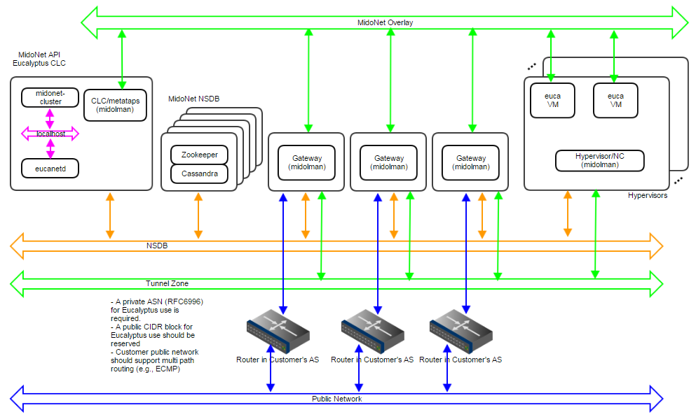 Figure 9: Production:Large deployment topology. A 1Gbps IP network carries NSDB; a 10Gbps IP network carries Tunnel Zone traffic; and another 10Gbps IP network carries Public Network traffic. A 5-node cluster for NSDB tolerates 2 server failures, and 3 gateways enable network failover and load balancing/sharing. Servers are bound to MidoNet in a way similar to Production:Small.
NSDB Data Replication
- NSDB is deployed in a cluster of 5 nodes
- ZooKeeper and Cassandra both have built-in data replication
- Up to 2 server failures tolerated
MidoNet Gateway Failover
- Three paths are available to and from MidoNet, and failover is handled by BGP
MidoNet Gateway Load Balancing/Sharing
- Load Balancing from MidoNet is implemented by MidoNet agents (Midolman): ports in a stateful port group with default routes out are used in a round-robin fashion.
- The customer AS should handle multi path routing in order to support load sharing/balancing to MidoNet; for example, Equal Cost Multi Path (ECMP).
7.2 - Verify Connectivity
Note
Any firewall running on the CC must be compatible with the dynamic changes performed by when working with security groups. will flush the ‘filter’ and ’nat’ tables upon boot.Verify component connectivity by performing the following checks on the machines that will be running the listed Eucalyptus components.
Verify connection from an end-user to the CLC on TCP port 8773 Verify connection from an end-user to Walrus on TCP port 8773 Verify connection from the CLC, SC, and NC to SC on TCP port 8773 Verify connection from the CLC, SC, and NC to Walrus on TCP port 8773 Verify connection from Walrus and SC to CLC on TCP port 8777 Verify connection from CLC to CC on TCP port 8774 Verify connection from CC to NC on TCP port 8775 Verify connection from NC to Walrus on TCP port 8773. Or, you can verify the connection from the CC to Walrus on port TCP 8773, and from an NC to the CC on TCP port 8776 Verify connection from public IP addresses of Eucalyptus instances (metadata) and CC to CLC on TCP port 8773 Verify TCP connectivity between CLC, Walrus, and SC on TCP port 8779 (or the first available port in range 8779-8849) Verify connection between CLC, Walrus, and SC on UDP port 7500 Verify multicast connectivity for IP address 239.193.7.3 between CLC and UFS, OSG, Walrus, and SC on UDP port 8773 If DNS is enabled, verify connection from an end-user and instance IPs to DNS ports If you use tgt (iSCSI open source target) for EBS in DAS or Overlay modes, verify connection from NC to SC on TCP port 3260